

 By Coco
Different cavity mechanisms require different engineering responses.
Gas porosity vs shrinkage porosity is an important distinction because the same visible symptom can lead to very different corrective actions. Both can reduce the usable section or appear after machining. Neither should be diagnosed solely from the word porosity on a rejection note; examine the cavity, its location and the process history.
Understand the mechanisms
Gas-related pores can arise from gases in the metal or gas introduced through filling, molds and cores. Shrinkage porosity relates to volume change during solidification when liquid metal cannot adequately feed a region. The details vary with alloy and process, and both mechanisms may be present in one component.
Rounder cavities may suggest gas, while irregular interconnected voids can suggest shrinkage. These are useful observations, not infallible rules. Surface preparation, section location and interacting mechanisms can complicate appearance, so further evidence may be needed.
Map the location against the method
Shrinkage-related issues often deserve a review of heavy junctions, isolated masses and the last regions to solidify. Compare the indication with the feeding arrangement and any simulation evidence. Adding a vent is unlikely to correct a region that lacks liquid feed during contraction.
Gas-related investigations may consider melt handling, moisture, binder decomposition, venting and filling turbulence. The relevant factors depend on the route. A high-pressure die casting and a sand-cast steel housing do not share an identical checklist or corrective recipe.
Inspect in the relevant condition
Machining can reveal cavities under an apparently acceptable surface. If the part includes sealing faces or pressure connections, inspect and test in the stage specified for acceptance. A raw-casting visual check cannot demonstrate the quality of material exposed later.
Select examination methods with suitable sensitivity and coverage. Radiography, CT, sectioning or other methods may support an investigation, but the choice should follow the material, geometry and question. A test that records indications still needs an agreed acceptance basis.
Avoid corrective-action shortcuts
| Suspected mechanism | Review first | Avoid assuming |
|---|---|---|
| Gas-related pores | Melt, mold/core gas and filling conditions | More pressure or one additive fixes every case |
| Shrinkage-related pores | Feeding path, thermal junctions and solidification | A smoother exterior proves internal improvement |
| Mixed or uncertain pores | Location, morphology and production records | One photograph provides a complete diagnosis |
Establish an application-based decision
The effect of a pore depends on location and function. A small discontinuity near a fatigue-sensitive surface can matter differently from one in a noncritical mass. Pressure retention, machining exposure and cosmetic requirements can also lead to different acceptance decisions.
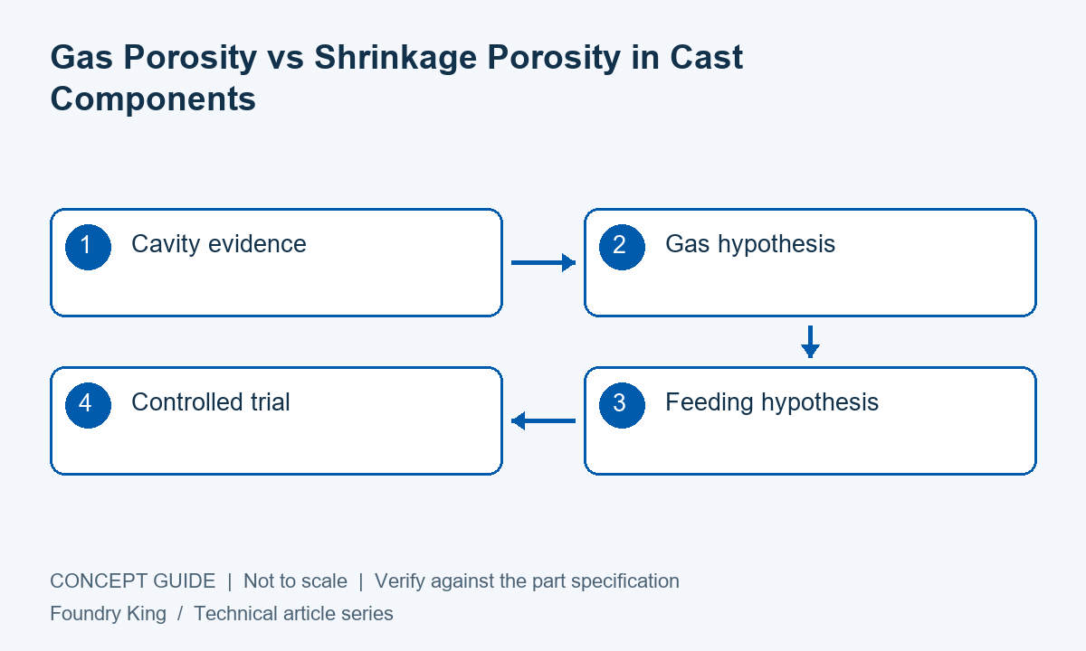
Document the investigation and run a controlled trial to validate the proposed correction. If impregnation or another treatment is considered, confirm whether the component specification permits it and what it can actually demonstrate. It must not be used silently to bypass an integrity requirement.
Frequently asked questions
Does every smooth round pore prove dissolved gas?
No. Appearance is one clue, and other evidence is needed when mechanisms or processing effects overlap.
Can porosity be assessed by hardness testing?
Hardness measures a different material characteristic and does not establish the absence or acceptability of internal cavities.
Discuss your component requirements
For related information, review aluminum casting information, or review porosity and inspection requirements. Include the drawing revision, alloy, quantities and critical acceptance requirements so the proposed route can be reviewed against the actual part.

Get Premium Casting Products
Join foundryking.com Newsletter to get more information of different premium OEM Casting products in China.


