

 By Coco
Improve manufacturability without losing the interfaces and load paths the component needs.
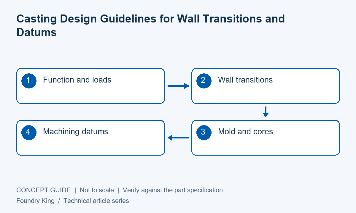
Casting design guidelines work best as a review of the actual drawing, not as a universal list of minimum dimensions. The alloy, molding route, component size and operating duty influence what is practical. Begin with the required function, then examine how the part will fill, solidify, leave the mold and reach its final machined condition.
Review abrupt changes in section
Heavy intersections and isolated bosses can create local thermal masses that are difficult to feed. Thin extensions may lose heat before filling. Gradual transitions and appropriate fillets can improve the design, but the correct geometry must also preserve mechanical performance.
Do not add thick material everywhere as a safety measure. Extra mass can increase cost and introduce new solidification problems. Discuss the load path with the designer and the feeding strategy with the foundry so that structural and manufacturing decisions support each other.
Make mold withdrawal feasible
Parting lines, draft and undercuts determine how the pattern or tooling can release. A seemingly small side feature can require an additional core, loose piece or die action. Identify these implications early enough to compare a simpler geometry with the original design.
Where appearance or assembly restricts parting witnesses and gate scars, mark those limitations. The foundry needs to know which surfaces are protected and where finishing is allowed. A permitted witness location can avoid unnecessary blending on a more sensitive feature.
Design cores for more than shape
Internal cavities require support, dimensional control, gas management and removal of residual core material. A passage that is easy to model may be difficult to manufacture or clean. Ask how it will be inspected, particularly if external measurements cannot reveal core movement.
If access openings are proposed, review their effect on sealing and service. Keep all changes controlled in the drawing and model. Manufacturing convenience should not introduce an undocumented plug, leak path or assembly interference.
Plan the machining sequence
| Review area | Question to resolve | Practical outcome |
|---|---|---|
| Walls and junctions | Can the section fill and be fed? | Fewer avoidable thermal hot spots |
| Pattern and cores | Can it be formed, supported and cleaned? | A feasible repeat-production method |
| Datums and stock | How will the raw part be located? | Reliable cleanup of functional surfaces |
Close the review with evidence
Record which dimensions are as-cast and which are machined. Agree the sample inspection and any required internal or functional checks. If a feature is beyond routine capability, decide whether to redesign, machine or qualify a special process before the order is released.
The most useful DFM output is a marked-up drawing and agreed action list. It should show the reason for each change and the customer’s approval where function is affected. This gives production a clear baseline and avoids relying on undocumented conversations during repeat orders.
Frequently asked questions
Can one set of rules cover every casting process?
General principles help, but detailed limits depend on the alloy, geometry, tooling and qualified process.
Is DFM only the foundry’s responsibility?
The foundry advises on manufacturing, while the equipment designer retains responsibility for function and approves changes affecting the application.
Discuss your component requirements
For related information, review sand casting design and cost considerations, or request a drawing review. Include the drawing revision, alloy, quantities and critical acceptance requirements so the proposed route can be reviewed against the actual part.

Get Premium Casting Products
Join foundryking.com Newsletter to get more information of different premium OEM Casting products in China.


