

 By Coco
Use tool-free mold geometry where it solves a real development problem.
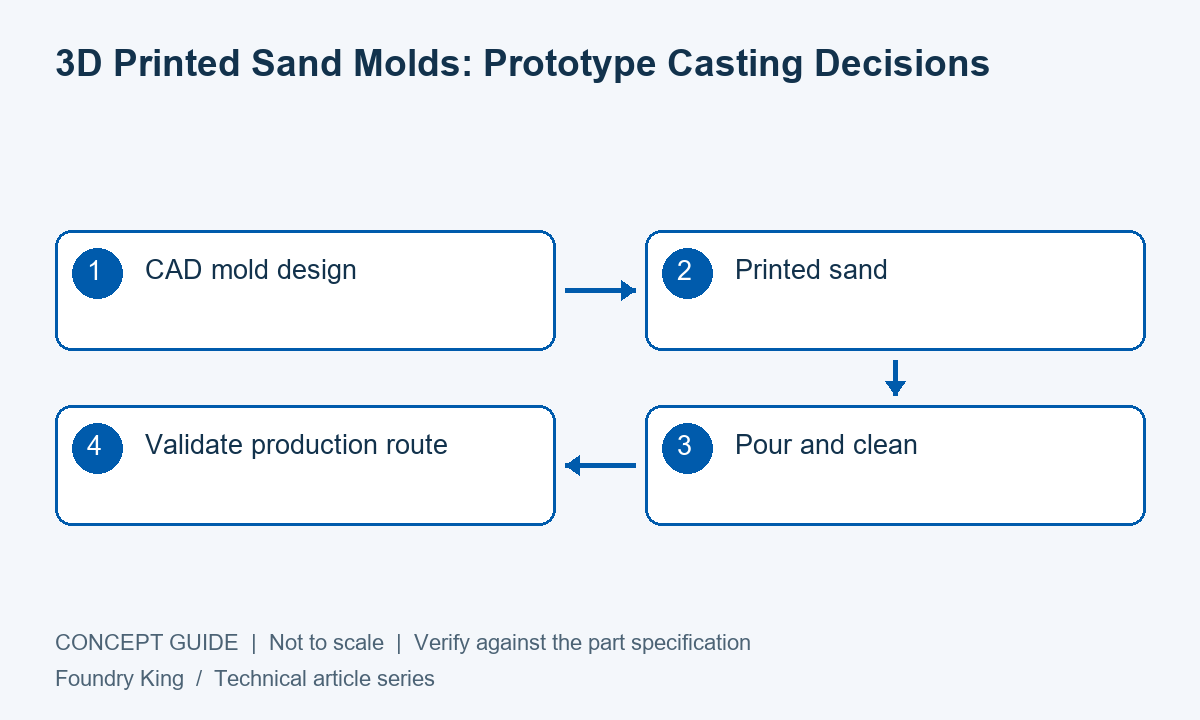
3D printed sand molds can remove the need for a conventional pattern when developing some metal castings. The sand mold or core is printed from a digital model, while the metal still solidifies through a casting process. This distinction matters: tool-free mold production does not remove the requirements for filling, feeding, alloy control or inspection.
Identify the development benefit
The strongest use case is often a changing geometry, a complicated core package or a prototype needed before hard tooling is justified. Printing can make certain internal shapes easier to produce, but a complex shape still needs to be cleaned and inspected after casting. A passage that traps loose sand may remain impractical even when it is printable.
Compare the printed route with the complete conventional option, including pattern preparation, core assembly and likely design changes. For a stable, simple component in repeat production, conventional tooling may remain economically attractive. Evaluate the decision using order quantities and revision frequency rather than assuming additive methods are always faster or cheaper.
Design the mold, not only the component
The printed model includes the mold cavity, core support, gates and feeding features. These elements must suit the alloy and pouring arrangement. A CAD file of the finished part is therefore an input, not a complete production mold design.
Ask how surface condition, binder system and post-print handling affect the pour. Fragile sections can be damaged during transport or assembly. Agree who approves the production mold design and how revisions are controlled when simulation or sample results lead to changes.
Define what the prototype proves
A printed-sand sample can verify geometry, assembly and an initial casting concept. It may not demonstrate the dimensional variation or surface condition of a later production molding line. If the final process changes, identify which requirements need fresh first-article approval.
This is especially important when prototype cores are printed but production cores use dedicated tooling. The support, assembly and gas behavior may differ. Keep the prototype’s purpose explicit so that successful assembly is not mistaken for full process qualification.
| Question | Why it matters | Evidence to request |
|---|---|---|
| Can the sand be removed? | Closed passages can trap residue | Cleaning demonstration or suitable inspection |
| What changes for production? | Printed and tooled routes differ | Documented transition plan |
| How is geometry measured? | Complex internals may be inaccessible | Agreed CT, sectioning or alternative method |
Use the trial to improve the drawing
Capture any changes to wall transitions, core access and machining datums discovered during the trial. Feed these changes into the controlled drawing before releasing production tooling. Otherwise, the same issue can reappear when a different engineer rebuilds the tooling model from an older file.
Keep the material and finishing route aligned with the intended application. A prototype poured in an easier alloy may demonstrate shape but not the behavior of the final specified metal. Clearly label such limitations in the sample report and purchase documentation.
Frequently asked questions
Is this the same as directly 3D printing the metal part?
No. The printed item is the expendable mold or core. Molten metal is subsequently poured into it.
Can a successful printed-mold prototype approve a conventional production line?
It supports development, but line-specific capability and repeatability still require appropriate validation.
Discuss your component requirements
For related information, review review alternative casting routes, or discuss a prototype and production plan. Include the drawing revision, alloy, quantities and critical acceptance requirements so the proposed route can be reviewed against the actual part.

Get Premium Casting Products
Join foundryking.com Newsletter to get more information of different premium OEM Casting products in China.


